Amphibious Insect Robot
For a CAD Challenge, I designed the chassis and mobility system of an insect-inspired robot based on the MiniWhegs series developed by Case Western Reserve University's biologically inspired Robotics lab. My final design measured 190x90mm, supported 4-wheel steering (4WS) and 4-wheel drive (4WD), with a turning radius of 160mm and a weight of 203 grams.
Drawing from my nautical background, I also aimed to make the robot amphibious. This required considerations of buoyancy, floatational stability, sealing, and rudder steering for feasibility.
Drive System
Calculating required power
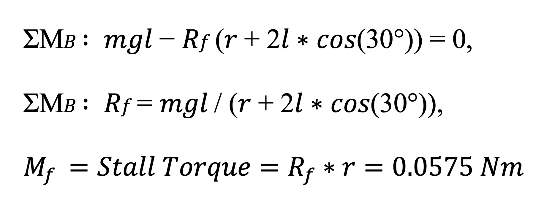
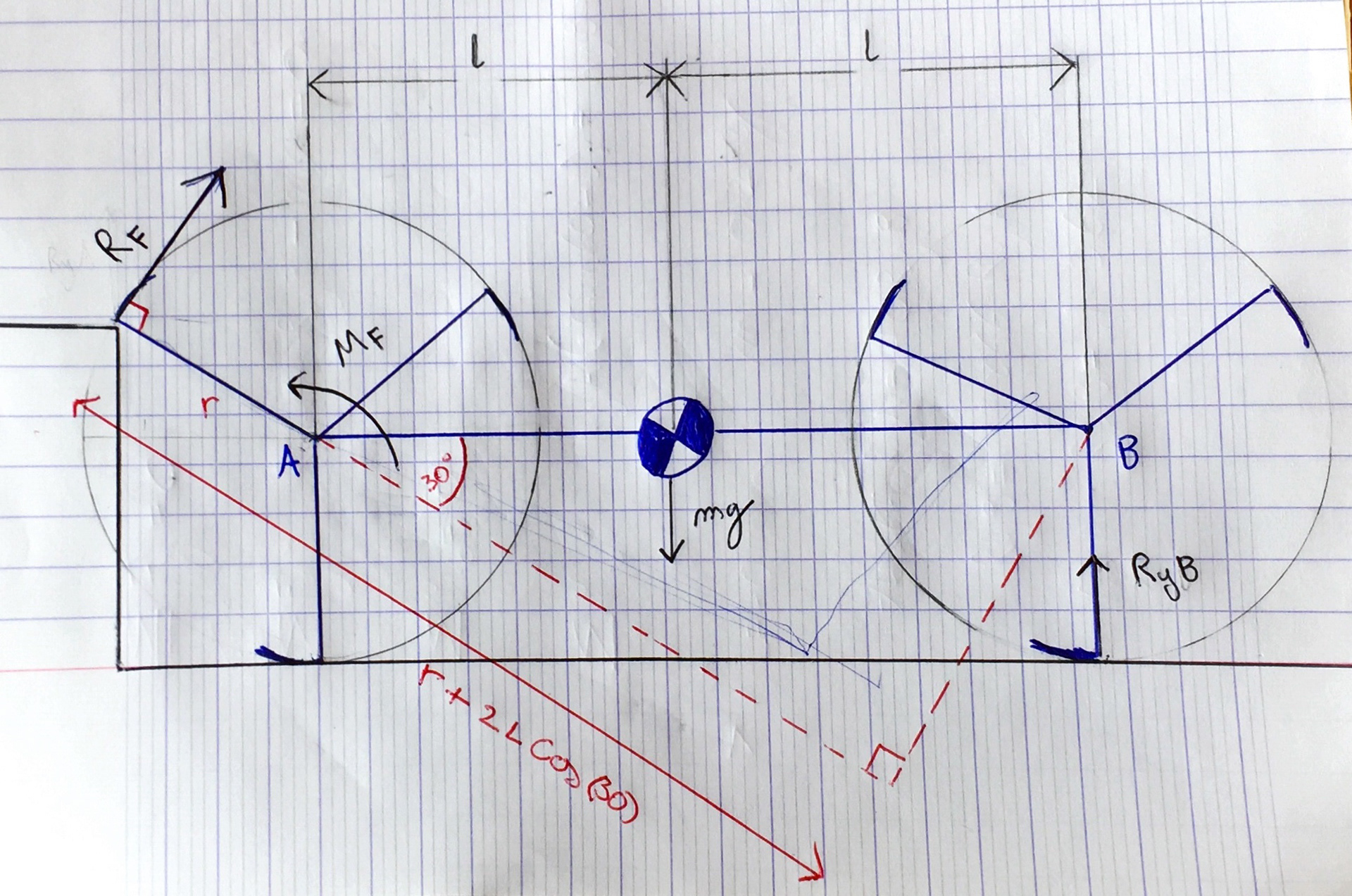
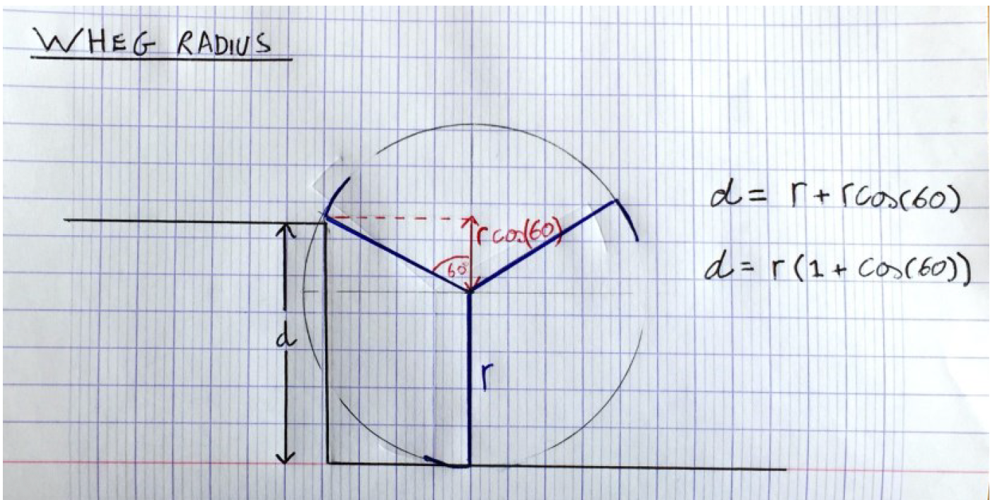
The first step to selecting a motor is to identify the required power - a function of both torque and rpm. A free body diagram was used to find the reaction force Rf in a worst case scenario. Subsequently the moment Mf was able to be identified as the stall torque. A healthy safety factor used to avoid the motor from stalling.
Gearbox Design
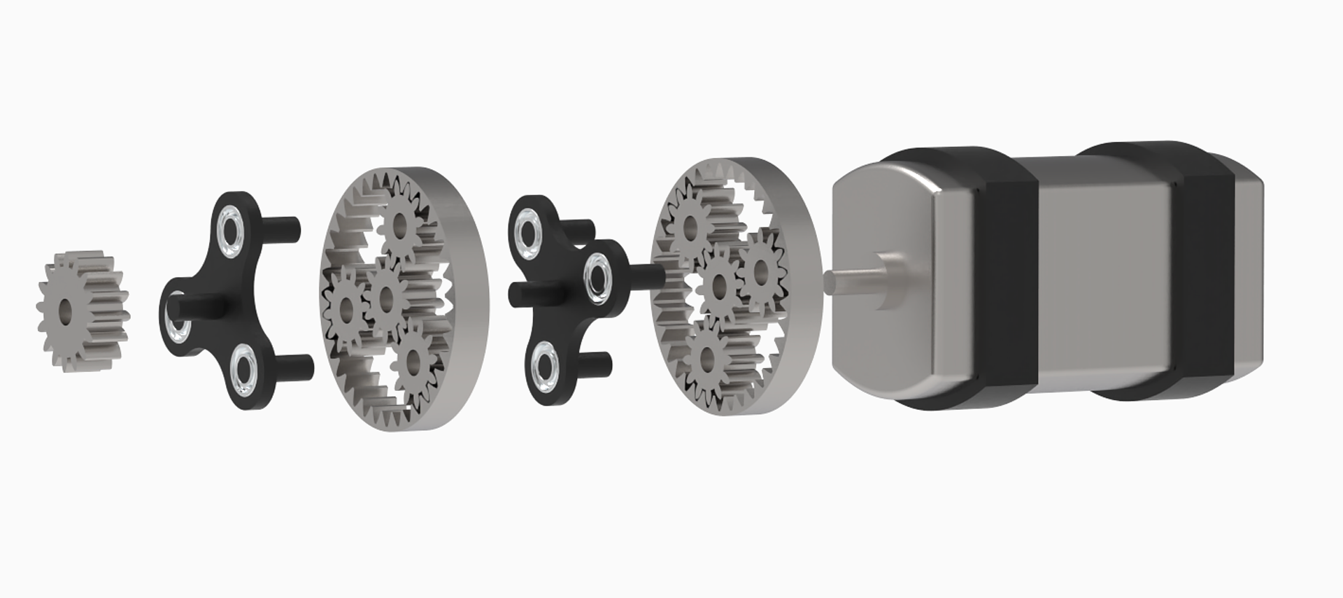
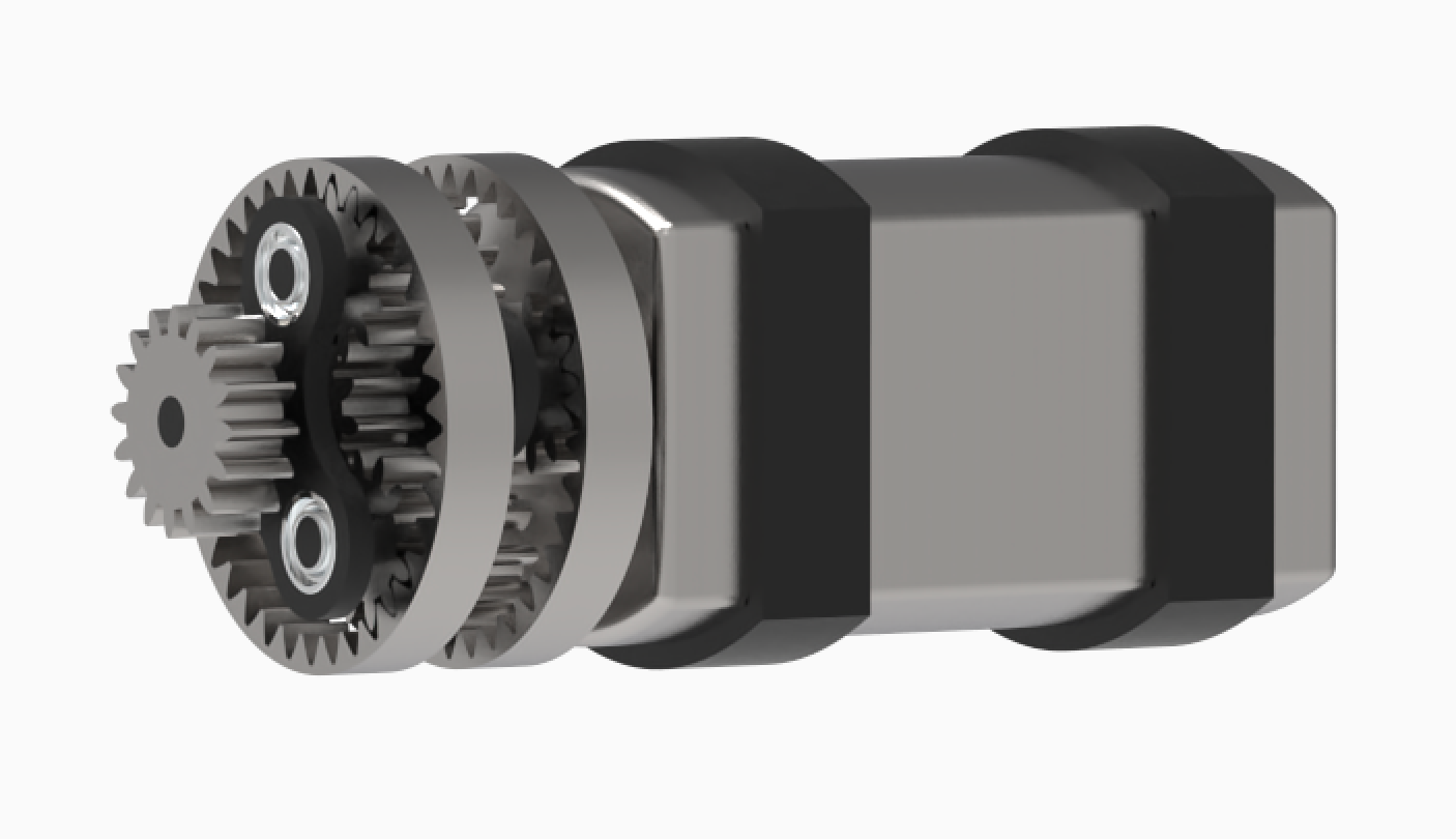
Once the motor specifications were identified, a gearbox needed to be created to step up the torque and step down the RPM. An epicyclic gearbox was used as they provide high load and compactness in comparison to the standard offset parallel axis gears. A 2 stage coupled planetary arrangement was designed whereby the ring gears were fixed:

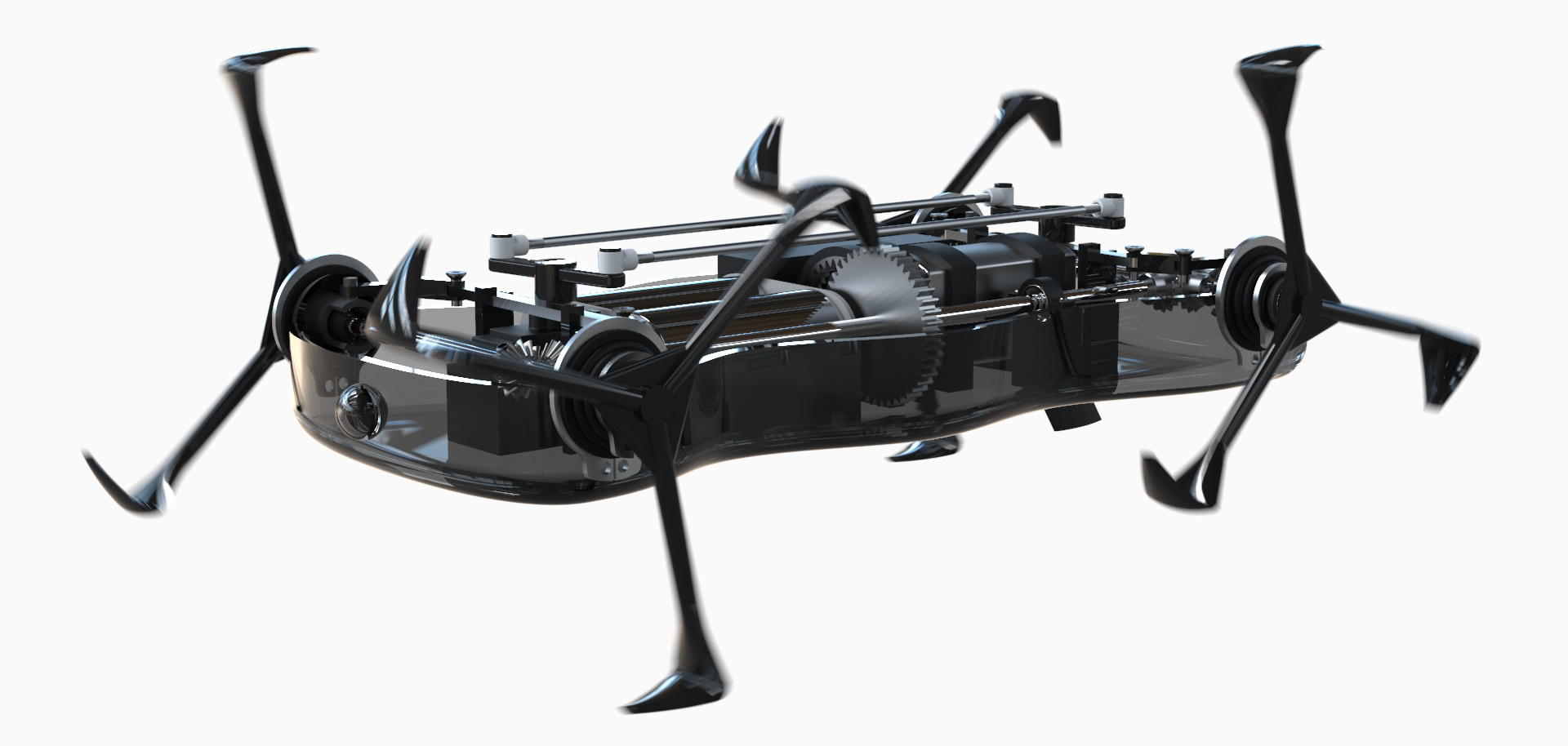
Drive train
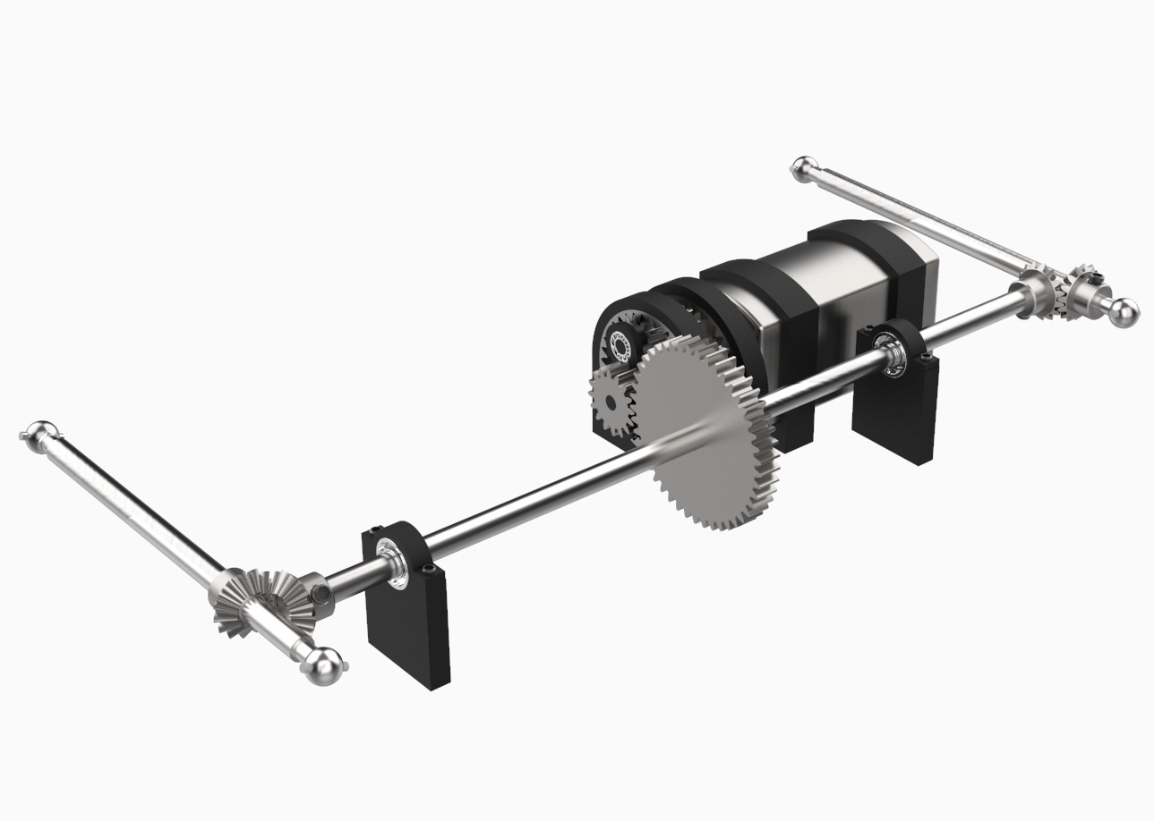
Below shows the final arrangement of the drivetrain. A total torque step of 34.2 was achieved (considering all gear inefficiencies).

Steering System
4 Wheel Steer & Rudder Control:
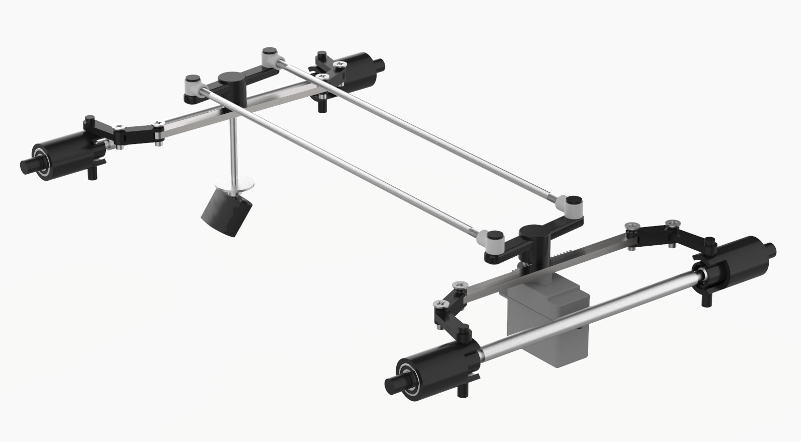
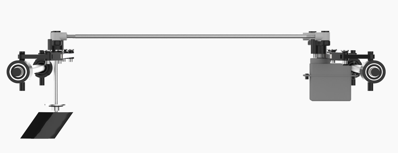
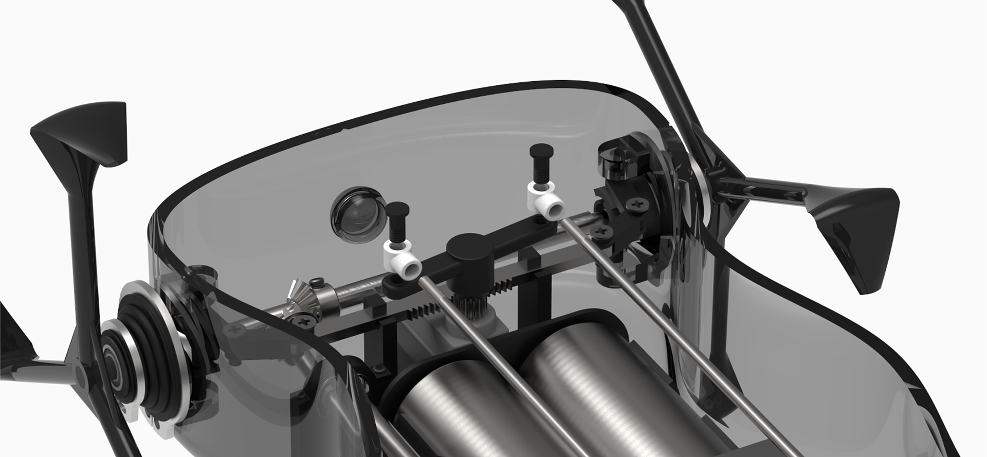
The mechanism below shows how 4 whegs & a rudder can all be controlled in phase with one anther. A servo motor controls the forehead rack and pinion, these are connected to push-rods that control the stern pinion. The stern pinion is also to the rudder. This arrangement is fully symmetrical about the centerline of the robot - maintaining it’s floatation stability.
Yoke and Spindel
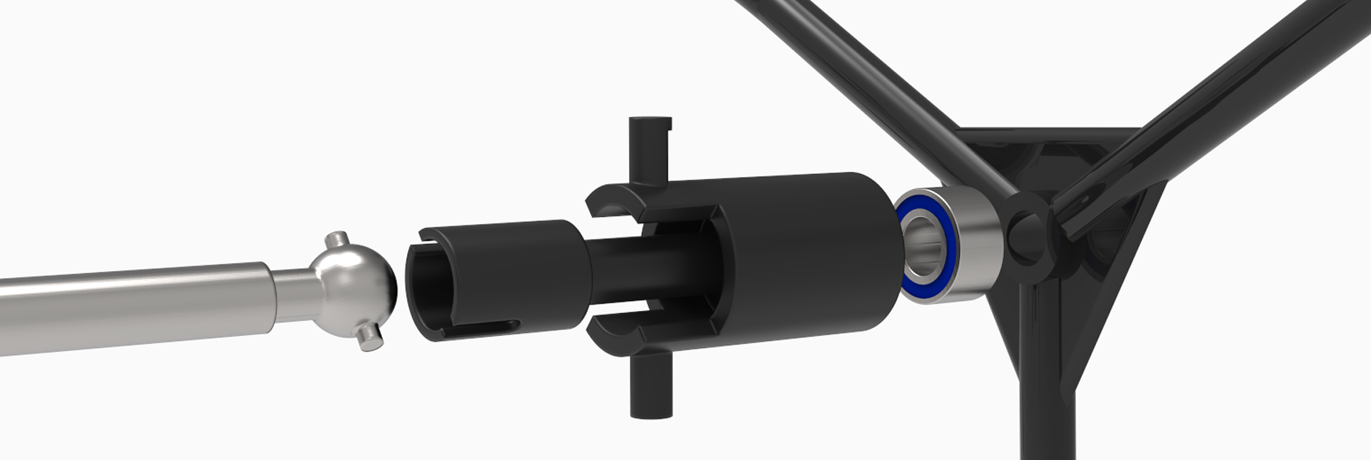
In order for the whegs to be driven as well as being able to steer, a universal joint needs to implemented in the end each axel. A typical solution that is used in RC cars is the dog bone and cup. This is a simplified universal joint that uses a fraction of the space of a typical yoke and spindle.
Waterproofing & Floatation
Adapted Micro Boot Axel for RC Cars
The steering mechanism provided a challenge for a fully amphibious robot. The nature of the universal joint requires a relatively large opening in the casing to allow for the rotational movement of the wheg. As this opening lies directly on the waterline, a method of sealing the opening is required without restricting the movement of the whegs. Shown below are micro-boots for sealing RC cars and their application for sealing the axle in my design.
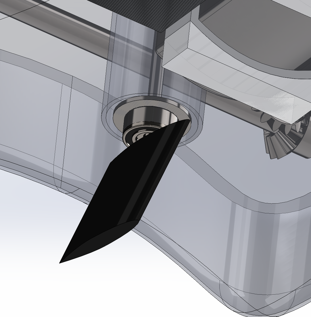
Rudder Shaft
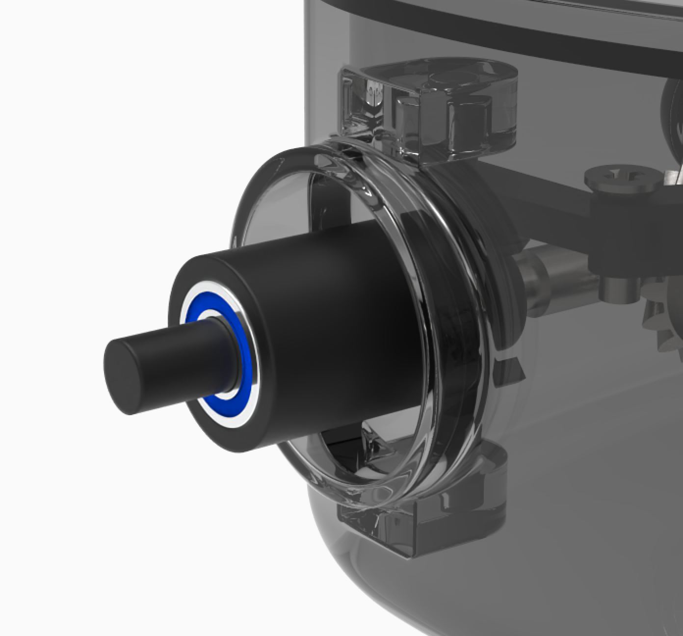
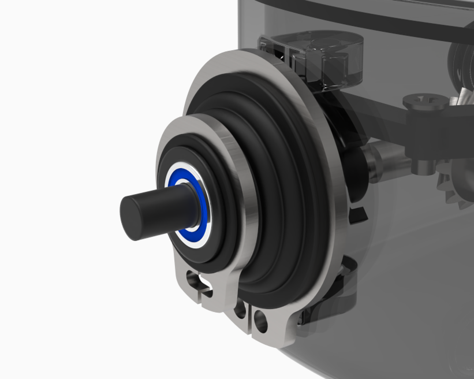
Sealing the rudder shaft was a much simpler process as the movement is restricted to just a rotation about the shaft axis. A sealed bearing was fixed in the bottom of the casing and cylindrical reservoir was created around it. The purpose of this reservoir is to prevent possible leakage from flowing throughout the rest of the hull whereby the electronic components lie. The top of the reservoir also houses a bearing that supports the rudder shaft.

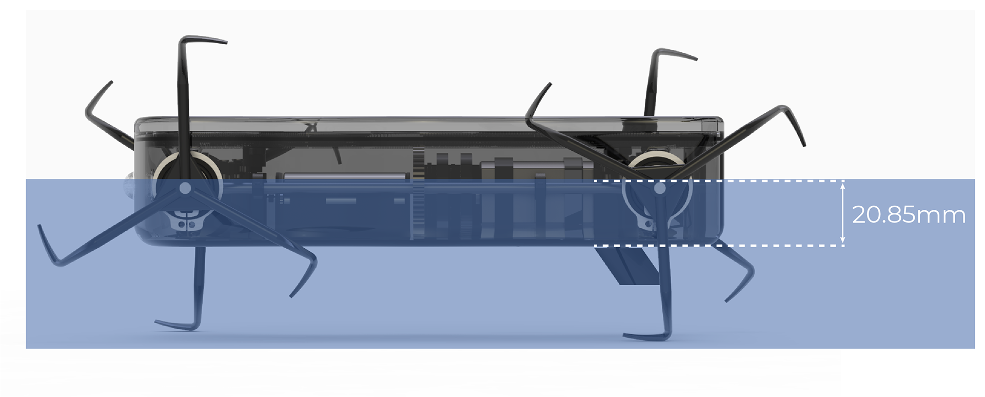
Floatation and Waterline
In order for the robot to paddle effectively the axels should be as close to the water line as possible - this is to reduce the drag that is produced from the whegs when rotating back to the forward positions. Archimedes principal on buoyancy was used to establish how much the robot draws in freshwater. This states that the volume of water displaced by a fluid is equal to the mass of that body divided by the fluid density.